Attention everyone who wants to build my circuit: I previously failed to consider current flow through sneak-paths in adjacent digits when more than one are connected in a multiplexing scheme. This wouldn't be a problem with LEDs, but current can flow both ways through the coils!
To prevent this from happening, a diode must be added in series with each coil (not the coil common!) . You will need 14 diodes per digit. Use a general purpose rectifier like the ubiquitous 1N4001, 1N4002, etc. These are popular 1A silicon diodes, differing only by their reverse voltage (PIV) ratings. The 1N4001 is good up to 50 volts.
I have seen pictures of some vane displays that already include a companion PCB containing such diodes. If you have one, don't throw it away! (Check the diode polarity, however)
Figure 1 has been updated to include the diodes. The rest of the figures are OK.
(Thanks, and a tip o' the hat, to commenter"Zapro")
===============================================================
Recently, I answered a forum question on the Adafruit Industries site regarding Vane Displays. Someone managed to score a few of these at a Ham Fest, and was asking how to make a clock project with them using an Arduino. (View forum topic here)
The same fellow (named for a Black Cat somewhere in Nashville?) also posted to Dangerous Prototypes, who was kind enough to feature this solution on their front page today! (31 Aug, 2011) Thanks, Ian!
So, anyway...
The displays in question are of a 7 segment electromechanical design. These are not light-up displays, but rather, reflective. Each segment is a "vane" that has been painted a bright contrasting color, and mounted on a hinge, such that it can be swung into, or hidden from view. This is accomplished with two solenoid coils sharing a common pin. In order to show a segment, the Show coil must be pulsed for about 50mS, which will flip the vane into view. A permanent magnet keeps it there, even after the coil is switched off. To hide the segment, just pop the Hide coil for 50mS. Pretty simple, no?
So, anyway, Figure 1, shows how to prepare each digit for use in this project. As stated earlier, vintage vane displays come in all shapes and sizes, and if you're lucky, there will be isolation diodes included, but if not, you must add them. Build up each digit to the diagram below:
 |
| Figure 1: Preparation of a Single Vane Digit |
Next, is a sketch that shows how to hook up the display to some driver circuitry. Since several of these will be used, a multiplexing scheme will be employed.
For clarity, Figure 1, above, has been reduced to a single black box, with the show and hide coil connections grouped together.
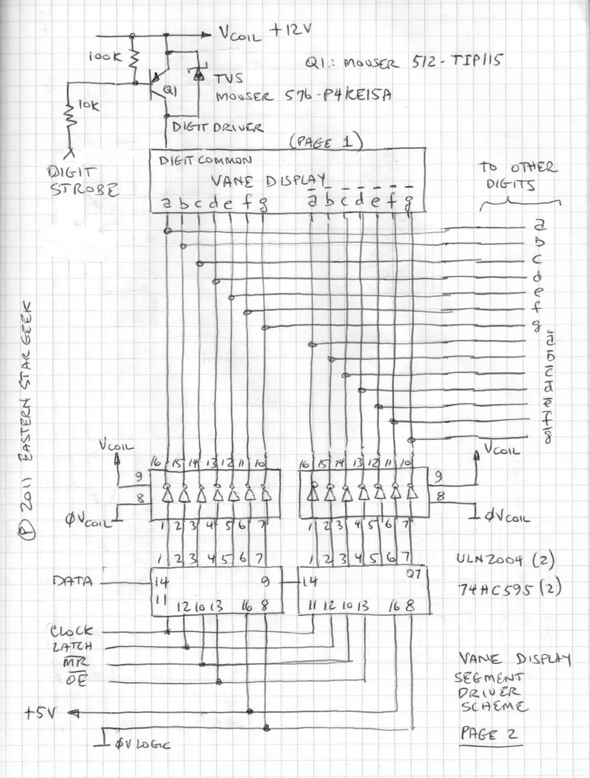 |
| Figure 2: Driving the Display Coils |
At the bottom are 14 low-side Segment Drivers, consisting of a pair of ULN2004 darlington transistor arrays.
Two ULN2004s are needed, one for the Segment (show) coils, and the other for the "anti-Segment" (hide) coils. I previously toyed with a few different schemes, but I think this one will look the nicest in operation, since all vanes belonging to a single digit will be able to change state simultaneously. The logic signals to each ULN2004 come from a pair of 74HC595 serial-to-parallel latching shift registers, using a well-known scheme for Arduino Output expansion. (See documentation at the Arduino website, http://www.arduino.cc/en/Tutorial/ShiftOut.
Note that each ULN2004 contains 7 channels, while the 74HC595 handles 8 bits, so Bit 0 (pin 15) of the 'HC595s is not used. For the following examples, data must be clocked into the shift registers Most Significant Bit, (MSB) first.
Since the switched loads are inductive, a high-voltage negative spike (Back-EMF) will be generated when they are switched off. This spike can easily smoke sensitive semiconductors, so two means of protection are necessary: The first uses the built-in protection diodes of the ULN2004, since this IC is designed for driving inductive loads. For these diodes to be able to do this very important job, however, pin 9 (common) MUST be tied to the Load (coil) supply. If we weren't using a digit driver at the top, no further protection would be necessary, but we are, so a TVS (Transient Voltage Suppressor) diode is wired across the PNP transistor as shown.
This diode is a ruggedized zener that will start to conduct when the reverse voltage exceeds 15 volts, opening a path through which the spike can be safely dissipated. Such diodes are very handy- being available in a wide range of voltages. Care must be taken to select the right part so that it won't conduct under normal operation!
Since additional digits will be multiplexed, no further segment drivers are necessary, no matter how many digits are added, since each one will be individually updated. These four ICs are enough for an entire six digit clock (and then some).
Now, on to Sketch 3, which shows how to connect multiple digits to the segment drivers:
 |
| Figure 3: Multiplexing Scheme |
Note that each digit does require a complete Digit Driver circuit, however. In the next sketch, we will show how to connect the Digit Drivers to the Arduino.
 |
| Figure 4: Digit Selection and Connections to the Arduino (Note: Ignore the bar over Y0-Y7 of the 74HC238) |
The 'HC238 is a great chip for this application, because it saves Arduino I/O, and only one output at a time can be energized, eliminating the possibility of overloading the ULN2004 if a software bug tries to select more than one digit at a time. The chip will use 3 Arduino outputs, which must produce a binary code to select a digit: 001=Digit 1, 010=Digit 2 ... 110=Digit 6. (Codes 000 (Y0) and 111 (Y7) are not used).
The black box at the bottom of the sketch (Latch Circuit) was detailed on Page 2. Here, we see how to hook up the logic signals to the Arduino. The /MR (Master Reset) is connected to a passive RC differentiator, which will apply a short negative-going pulse upon power-on, clearing the shift registers of any garbage that might be present. If you want, you can connect this line to another Arduino output.
Finally, because this will hopefully be a real circuit someday, real construction techniques must be used! The last sketch shows how to distribute the DC power for the Coil circuits, as well as the Logic circuits. Please follow this carefully, to avoid frustrating problems caused by noise and transients.
 |
| Figure 5: Power Distribution Method |
So there you have the hardware!
==================================================
Tackling the software!
So, now we need to start thinking about how to develop the code that will make these lovely displays do what they were designed to do.
The first thing is to examine the limitations of the hardware. Multiplexing is great because it saves wiring, glue chips and I/O, but it also means we can only update one digit at a time. Since the vanes require about 50mS to flip, we cannot scan the digits faster than that. If only one digit at a time is being changed, nobody will know, but at midnight, all 6 will change, making a lovely "thup-thup-thup-thup-thup-thup" sound. Arguably, that is part of the charm of this vintage technology!
So, anyway- the next thing to consider is that there is no regular relationship between digital integers and the segment patterns required to display them. Therefore, our code must use a Lookup Table to map the required segment patterns onto a 16 bit word (data type unsigned int). Take a moment to review the sketch on Page 2. The segment data is being clocked into the two shift registers, but it will originate from a 16 bit word in the Arduino. Since Bit 0 (Pin 15, Q0) of neither SR chip is used, bits 1 - 7 will drive the Show Coils a - g, respectively, and bits 9 -15 drive the Hide Coils, /a - /g.
Finally, when a digit is updated, all segments to be shown must get a "1" and so must all segments that will be hidden.
What we will do, is use the character to be displayed as an index (0 - 9) into a 1-dimensional array of 11 unsigned integers. (Index 10 will be used to blank a digit). The structure of the lookup table appears below:
 |
| Figure 6: Lookup Tabl;e, Segment Data |
Don't let the concept of a Lookup Table intimidate you. This is what it will look like in your Arduino sketch:
const unsigned int SegmentTable[11] =
{
0x807E, 0xF20C, 0x48B6, 0x609E, 0x32CC,
0x24DA, 0x04FA, 0xF00E, 0x00FE, 0x20DE, 0xFE00
};
See? Nothing to it!
Note that the organization of the lookup table must agree with the hardware! Looking once again at page 2, the two 74HC595 chips are hooked up in a sequential cascade. The very first bit (Bit 15) to be clocked-in will wind up at Hide Coil "/g." (Pin 7, Q7 of the right-hand chip)
The last bit (Bit 0) doesn't do anything, because the corresponding pin (Pin 15) of the left-hand chip isn't connected, but the next-to-last bit (Bit 1) to be clocked-in will wind up at Show Coil "a" (Pin 1, Q1 of the left-hand chip)
Don't forget, when you set up your Arduino ShiftOut procedure, be sure that the Most Significant Bit (MSB) gets clocked-out first!
 |
| Figure 7: Internal structure of the 74HC595 Shift Register |
Now, the more astute amongst you may have noticed that the required state of each "anti-segment" is always opposite of the segment state. Naturally, that begs the question, "Well, why not use only one shift register, and a 74HC240 octal inverter to drive the second ULN2004?"
Why, indeed? If you'd rather do it that way, have at it!
(The remaining post pertains only to the original double-shift register approach.)
Crawl, before you Walk!
OK, so now let us try testing a single digit. Wire up the circuit shown in Figure 2, above, except ignore the connections to other digits. We're just going to hook up one vane display and test it out. You will need:
12VDC, 1Amp Power Supply
Arduino of your choice (+5V operation)
Vane Display (1)
ULN2004 (2)
74HC595 (2)
TIP115 PNP Transistor
P4KE15A TVS Diode
2N2222 NPN Transistor
100K, 1/4W resistor (2)
10K, 1/4W resistor
4.7K, 1/4W resistor
470uF, 25V Electrolytic Capacitor
220uF, 25V Electrolytic Capacitor
0.1uF, 50V ceramic capacitor (2)
One more thing- because we're only testing one digit, we have to use a special version of the High-Side driver, diagrammed in Figure 8, below. Instead of a stage from the Hex Inverter in Figure 4, a discrete NPN transistor (Q2) is used instead. This ensures that the PNP transistor, operating at +12V can be properly controlled by the +5V Arduino logic signal.
 |
| Figure 8: Special Detail for Digit Driver, Single Digit Test |
When wiring this test circuit, see Fig 5, above for proper Power Supply connections
Connect the logic signals to your Arduino as follows:
a. Digit Strobe to Digital I/O 2
b. Shift Register Data to Digital I/O 11
c. Shift Register Clock to Digital I/O 12
d. Shift Register Latch to Digital I/O 8
e. /MR to +5V
f. /OE to GND
Try out this code, which will cycle the display from 0-9, blank, then repeat about once per second:
/*
Single-Digit counter, using Seven-Segment Vane Display
(Per instructions in EasternStarGeek's Blog:
http://easternstargeek.blogspot.com/2011/08/nifty-electromechanical-vane-display.html
Author: Eastern Star Geek, Johnson City, TN
Date: 26 August, 2011
This code will increment a single-digit Vane Display from 0 to 9, blank, then repeat
*/
const byte dataPin = 11; // Shift Register Data Pin
const byte clockPin = 12; // Shift Register Clock Pin
const byte latchPin = 8; // Shift Register Latch Pin
const byte digitStrobe = 2; // Digit Driver Strobe
// Lookup Table for Segment and Anti-Segment data
const unsigned int segmentTable[11] =
{
0x807E, 0xF20C, 0x48B6, 0x609E, 0x32CC,
0x24DA, 0x04FA, 0xF00E, 0x00FE, 0x20DE, 0xFE00 };
unsigned int segmentData; // Holds current Segment/Anti-segment Data
unsigned int Counter = 0; // Counter Value, 0 to 10
void setup() {
pinMode (dataPin, OUTPUT);
pinMode (clockPin, OUTPUT);
pinMode (latchPin, OUTPUT);
pinMode (digitStrobe, OUTPUT);
}
void loop() {
constrain (Counter, 0, 10); // Prevents bad data from being fetched
segmentData = segmentTable[Counter]; // Get segment data from Lookup Table
// Prepare Latch for Data Transmission
digitalWrite(latchPin, LOW);
// Shift out High Byte
shiftOut (dataPin, clockPin, MSBFIRST, (segmentData >> 8));
// Shift out Low Byte
shiftOut (dataPin, clockPin, MSBFIRST, segmentData);
// Assert Latch to transfer Data
digitalWrite(latchPin, HIGH);
digitalWrite(digitStrobe, HIGH); // Enable Digit
delay(75); // Allow 75ms for vanes to Flip
digitalWrite(digitStrobe, LOW); // Disable Digit
if (Counter < 10)
Counter = Counter + 1;
else
Counter = 0;
delay(925);
}
...More to come, Stay Tuned!
Did my comment just got deleted ?
ReplyDeleteI milled a PCB according to the schematics for 6 Pcs. of these Staver Signalex L152 displays.
Unfortunately, it does not work, as the current flows backwards trough the neighboring coils when firing a digit strobe.
I have modified the layout to use a 1N4148 on every single hide/show on the segments (14 for each digit) and then it works....
// Per.
Thanks, Per, and my apologies for not noticing this problem. Please be sure to come back and tell us how you made out!
ReplyDeleteI wonder if there couldn't be an approach where the line for segment 'd' being high, resulted in the "show" coil being energised and when the line for 'd' segment being low, resulted in the "hide" coil being energised, at least momentarily. With it not being sensible to energise both the "show" and "hide" for a segment at the same time, doesn't it make sense to have just one line for each segment? Even if it doesn't it would be easier to modify designs that were originally for 7 segment LEDs, if we only had one line for each segment. Or am I missing something?
ReplyDeleteYes, I already mentioned this when, as an alternative to a pair of shift registers and a 16 bit lookup table, you could use one shift register, an octal inverter, and an 8-bit lookup table to generate the drives for the "hide" coils. Either approach will work.
Delete